System diagram
The Simrad ME70 system comprises a computer, a transceiver, three linear power supply units, and the transducer. The transducer is often placed in a drop keel.
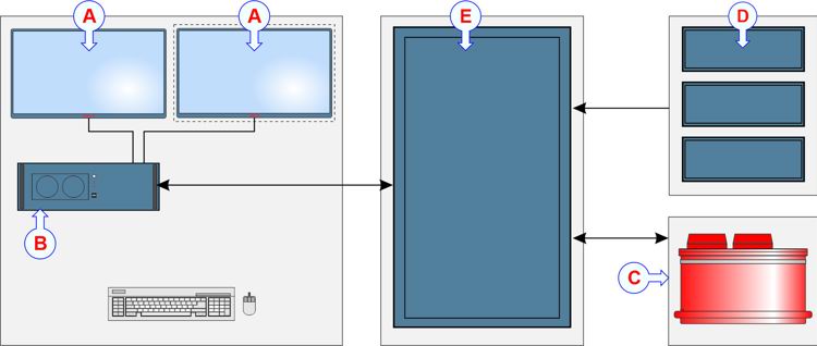
(A) Display (the second display is optional)
(B) Processor Unit (computer)
(C) Transducer
(D) Power Supply (3)
(E) Transceiver Unit
Installation drawings
Outline dimension and production drawings are provided in PDF and DWG formats. Use the link to open the drawings page in a new window.
Simrad ME70 Installation drawings
Display
A display is a required part of the multibeam system. Any commercial display can be used provided that it meets the minimum requirements. A large display with high resolution is recommended. The multibeam software supports all display sizes. The visual quality of the presentations depends on the quality of your graphic adapter and display. More than one display can be used. The display is not a standard part of the delivery. This is a commercial item that can be purchased locally.
Processor Unit
The Processor Unit comprises a single powerful maritime computer. It is provided as a standard part of the delivery. It serves several functions.
The Processor Unit handles the advanced signal processing required to present the information on the display, and it allows you to control the multibeam system. It provides the graphic presentation of the echo data, it holds the menu system, it communicates with the transceiver and reads information from the peripheral units. The Processor Unit is a marine computer using the Microsoft Windows® operating system. It is designed for rugged use and placed on shock absorbers. The computer is based on a commercial design, but the software and hardware have been specified and assembled specifically to meet the scientific multibeam requirements.
Transceiver Unit
The Transceiver Unit contains the transmission and reception circuitry for the multibeam system.
The Simrad ME70 transceiver is provided to transmit the acoustic energy into the water. To do this, the transceiver computes and generates the electric signals sent to the transducer to form a transmission - a 'ping'. After each transmission, it will receive the echoes from the targets in the water column and/or the seabed. These are filtered and amplified, and then converted to digital format.
The transceiver electronics is housed in a 19" rack. It contains 25 transceiver boards with a total of 800 individual channels.
Transducer
The Simrad ME70 is a short cylindrical container with 800 transducer elements.
The transducer converts the electric energy generated by the transceiver to physical vibrations. These vibrations alter the water pressure and create an acoustic pulse that is sent into the water. The acoustic signal is transmitted as a beam. The duration of the acoustic pulse, as well as its frequency and shape, are controlled by the transceiver. The direction and the opening angle of the beam is controlled by the transceiver and the physical properties of the transducer.
After the transmission, the transducer works as a "microphone". It converts the water pressure created by the acoustic echoes to electric energy. These weak echo signals are sent to the amplifiers in the transceiver.
The transducer must be handled with care. The red protective coating is a vital part of the transducer. It is very important that neither this coating nor the internal parts of the transducer are damaged during the handling, installation, or cleaning. Any holes and/or scratches in the transducer surface will allow water to penetrate the transducer. If a leak occurs, the transducer must be replaced.
The transducer must always be handled as a delicate item. Wrongful actions may damage the transducer beyond repair. Observe these transducer handling rules:
- Do not activate the transducer when it is out of the water.
- Do not lift the transducer by the cables.
- Do not step on the transducer cables.
- Do not damage the transducer cables, avoid sharp objects.
- Do not handle the transducer roughly, avoid impacts.
- Do not expose the transducer to direct sunlight or excessive heat.
- Do not use high-pressure water, sandblasting, metal tools or strong solvents to clean the transducer face.
- Do not damage the outer protective skin on the transducer.
Power Supply Unit
Three Power Supply Units are provided. Each unit provides operational voltages to a dedicated subracks in the Transceiver Unit.
The power supplies are controlled from the Processor Unit. The connection is made using three Ethernet cables from the Ethernet switch in the Transceiver Unit.